

Servo Motors
A beginner's guide to Servo Motors

Exploring
Hi there! So recently I was surfing the internet to gather some information about servo motors. Still, I couldn't find precise details regarding it, which didn't fulfill my motive. So, to make information regarding servos clearer, I have written this blog with the knowledge I gained and partly with the assistance of the internet. This blog contains all the essential details regarding the servos and a DIY project to practice yourself! I hope you will like it.
What are Servo Motors?
The term servo was first used by Joseph Farcot in 1859, who implemented a feedback mechanism to assist in steering a ship with steam to control the rudders. Servo motors are electromechanical devices accommodating rotary or linear actuators that rotate and push machine parts precisely, producing torque and velocity based on the supplied current and voltage. Servos are specialized for high precision and response positioning, are easily controllable, and their starting torque is high, so they are usually preferred industrially.

A servo motor is part of a servo mechanism consisting of three key elements – a motor, a feedback device, and a control device. A standard induction motor is rated in kW or HP, but a servo motor is rated at kg/cm; this is so because it shows how much load its shaft can carry per cm, or it represents the motor’s toque for a pulley at the radius of 1cm, and it gets weaker as radius increases. Usually, a servo motor is rated at 3 kg/cm, 6 kg/cm, and 12 kg/cm, the motors use a reduction gearbox which lowers the RPM (rotation per minute) and provides higher torque. In a servo motor, speed is determined by the frequency of the applied voltage and the number of magnetic poles. The servo motor has a rotation detector (encoder) mounted on the back shaft side to detect the rotor’s position and speed. This enables high resolution, high-response positioning operation.
Types of Servo Motors
A servo motor can be brushed or brushless and can be any size. A servo motor can have two types of current input AC or DC :
AC servo motors can handle higher current surges and are thus generally used in heavy industrial machinery where position control is critical and are frequently used in robotics, semiconductor equipment, machine tools, and aircraft. On the other hand, a DC servo motor is best suited for small-level applications with excellent controllability and feedback.
Generally, three basic types of servos are used:
- Positional Rotation Servo Motor: They rotate 180 degrees and have stoppers in the gear mechanism to protect the output shaft from over-rotating.
- Continuous Rotation Servo Motor: It is a servo that does not have a limit on its range of motion. Instead of having the input signal determine which position the servo should rotate to, the continuous rotation servo relates the input to the speed of the output and direction. The limitless motion of these motors enables them to move in both CW and CCW directions.
- Linear Servo Motor: It uses a rack and pinion mechanism to change its output. The rack and pinion convert rotary motion to linear motion.
Working and Structure of Servo Motor
Working of Servo Motors :
Servo motors work as a part of a closed-loop control system (feedback system), providing torque and velocity as commanded from a servo controller utilizing a feedback device/position sensors (Usually encoders for AC servo motors which are used in CNC (Computer Numerical Control) and VMC ( Vertical Machining Center) machines and Potentiometers in DC servo motors) to close the loop. The feedback device supplies information such as position, current, and velocity to the servo controller, which adjusts the motor action depending on the commanded parameters. The below represents the block diagram of the working of the feedback system.
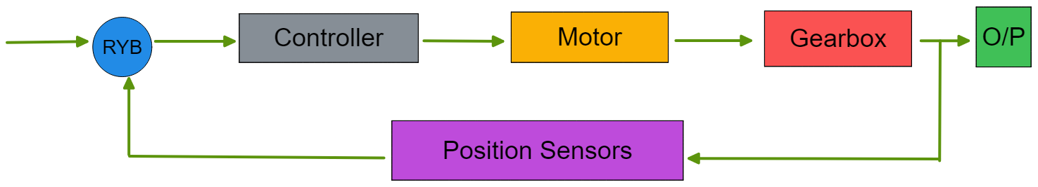
- The RYB or the power input is supplied to VFD ( variable frequency drive), the controller or servo driver that commands the motor's working.
- The controller is next connected to the motor.
- The motor is then connected to the gears (reduction gearbox), which provides low RPM and high torque, which is next connected to the O/P or the shaft.
- The gearbox is also connected to position sensors or the feedback system, which provides the information about the velocity, current, and position, which it provides to the control unit or the controller, which is next processed by the control unit to either stop or give the input to the motor.
Usually, when the motor works on lower RPMs such as 5 RPM or 10 RPM, the motor stops at the same point when the controller cut-offs the power, but in industrial motors, which work on 1,500 RPM and 3,000 RPM, the stopping of the motor or shaft at the same position is not possible. Hence, the system uses the braking system placed after the reduction gearbox to stop the motor/shaft from moving from the point when the controller cuts off the power.
Structure of Servo Motor :
The below figure shows the structure of AC servo motors:
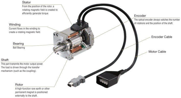
- Stator From the position of the rotor, a rotating magnetic field is created to generate torque efficiently.
- Winding Current flows in the winding to create a rotating magnetic field.
- Bearing Ball Bearing
- Shaft This part transmits the motor output power. The load is driven by the transfer mechanism (coupling).
- Rotor A high-function rare earth or other permanent magnet is positioned externally to the shaft.
- Encoder The optical encoder always watches the number of rotations and the position of the shaft.
- Encoder Cable transmits the data to the servo driver or the controller
- Motor Cable is used as the power supply to the motor. Here we usually get four pins, namely RYB, and the fourth pin is the earthing. Here all four pins are connected to the Servo Driver.
Use of Encoder: The encoder is a sensor for detecting the speed and position of the motor. Light from the light-emitting diode (LED) passes through a position detection pattern on the slit disk and is read by the light-receiving element. Dozens of phototransistors are integrated into the light-receiving part. All the absolute position detection designs depend on the encoder's rotation angle. The CPU is mounted on the encoder to analyze the absolute position detection patterns. The current position data is transmitted to the servo driver via serial transmission.
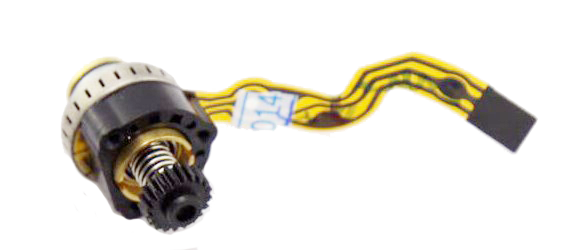
The 4-pin motor cables are usually seen in industrial or heavy-duty servo motors. Still, in small or light-duty servo motors such as SG90, used with an Arduino or other micro-controllers, there is no encoder cable as the potentiometer is attached internally to the motor. The Signal lead or the PWM pin is used as the input data to the servo from the micro-controller. The input cable consists of 3 pins :
- Red wire → Positive lead / Power
- Brown or black wire → Negative lead / GND
Yellow or orange wire → Signal lead / PWM
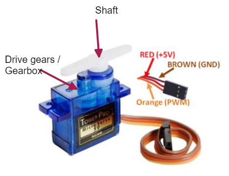
The above picture shows SG90 (9g) servo motors generally used with micro-controllers such as Arduino, raspberry pi, etc.
Controlling Servo Motors
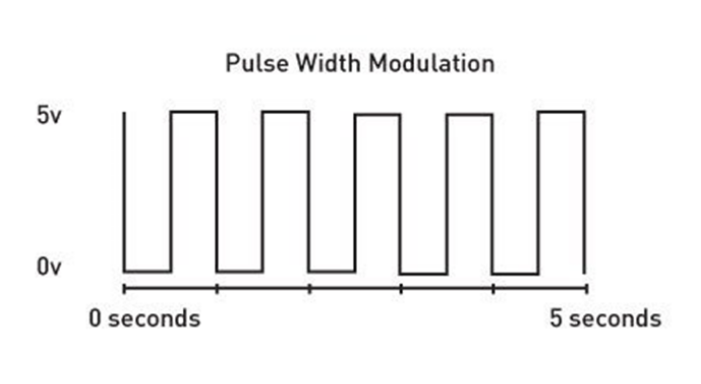
Servos are controlled by Pulse Width Modulation (PWM) that sends an electric pulse of variable width to the motor. With PWM, there is a minimum pulse, a maximum pulse, and a repetition rate. The rotor will turn to the desired position based on the duration of the pulse. When servos are commanded to move, they move to the place and hold it. The below graph is the pulse width modulation graph for Servo Motors :
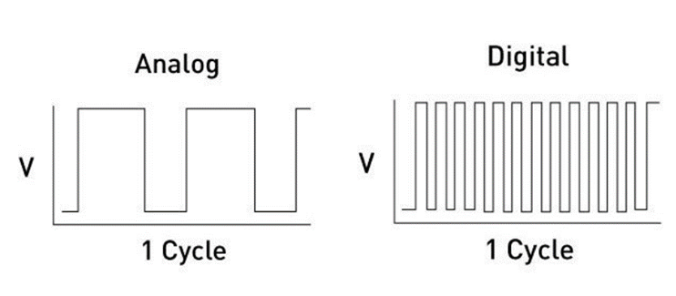
The Analog and Digital servo motors look precisely the same. The difference is in the way they signal and process information. Analog Servos operate based on voltage signals that come through the PWM. When an analog servo is at rest, the PWM is essentially off unless you transmit some action. Producing torque from the resting mode makes the initial reaction time sluggish. This delay in torque isn’t ideal for advanced applications.
Digital Servos use a small microprocessor to receive and direct action at high-frequency voltage pulses. The digital servo sends nearly six times the amount of pulses an analog signal does. These faster pulses provide consistent torque for quicker and smoother response times. It’s important to note that shorter pulses require more power emission from the motor. The below graph is for analog servo motor vs. digital servo motor pulse width modulation.
Application of Servo Motors
As servo motors are capable of accurate rotation angle and speed control, they can be used for various equipment.
- Tuning Free
- Compact and High Power
- Wide Variable Speed Range
- Standard or Planetary Geared Type
- Electromagnetic Brake Types
Generally, there are several applications of servo motors in our world; some of the examples related to the above topics are :
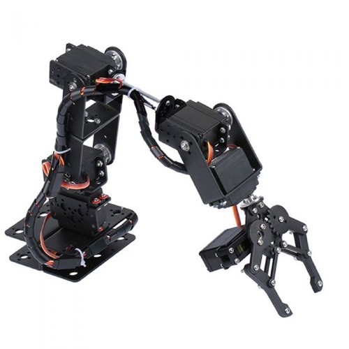
Robotics: Robotic arms and their movements need precision, so servos are attached to every joint of the robot giving it precise angle and movements.
Camera Auto Focus: A highly precise servo motor built into the camera corrects a camera’s lens to sharpen out-of-focus images
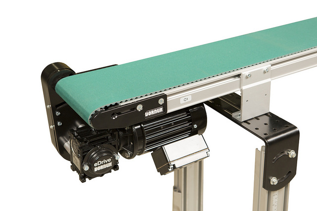
Conveyor Belts: Servo motors move, stop, and start conveyor belts carrying products through various stages, for example, in product packaging/bottling and labeling.

Antenna Positioning: Servo motors are used on both the azimuth and elevation drive axis of antennas and telescopes such as those used by the National Radio Astronomy Observatory (NRAO).
Advantages and Limitations of using Servo Motors
Servo Motors are boon to the industrial sector as well the general usage as it makes the machinery give output to the point, but there are also some limitations which make servos not used by the people all the time.
Advantages :
- Precision: Highly precise operations
- Speed: High speed and more torque in a small package
- Encoder: Translates rotary or linear motion to a digital signal
Servo Motors are always frequent and work at the same pace. So, if a heavy load is placed on the motor, the driver will increase the current to the motor coil as it rotates the motor. This means that servo motors are expected to always be mechanically on point. And because of its precision, it allows companies to operate it at a high-speed pace.
Disadvantages :
- High maintenance and operation costs.
When a machine using a servo is stopped, the motor continues to move back and forth one pulse, so it is not good if the device or area is unsuitable for vibrations.
DIY project using a Servo Motor :
We will now see how the servo motor works. We will create a simple example where we use PICO to rotate our servo motor from 0 to 180 degrees and vice-versa. Your system can also perform this using Tinkercad. For doing this project, we need :
- Arduino Board
- Servo Motor (SG90)
- Male-Female wires
- Bread-Board
Now, we will see the pinouts of the servo motor:
- Red wire → Positive lead.
- Brown or black wire → Negative lead
- Yellow or orange wire → Signal lead
Let's get started:
We will use pin nine as the signal lead to the servo motor for the controlling of the servo motor.
- Connect the signal lead to pin 9 using the breadboard via male wires
- Now connect the +5V and GND pins to the (red and black wires, respectively) to the servo motor using a breadboard.
- Our connection is completed. Lets move on to the coding part.
- Connect your Arduino board to the system/computer and upload the following code:
 #include <Servo.h>


   Servo myservo;     // create servo object to control a servo
   // twelve servo objects can be made on most boards

   int pos = 0;     // variable to store the servo position

void setup() {
      myservo.attach(9);     // attaches the servo on pin 9 to the servo object
}

void loop() {
      for (pos = 0; pos <= 180; pos += 1) {     // goes from 0 degrees to 180 degrees
                                              // in steps of 1 degree
   myservo.write(pos);     // tell servo to go to position in variable 'pos'
   delay(15);     // waits 15ms for the servo to reach the position
}
      for (pos = 180; pos >= 0; pos -= 1) {     // goes from 180 degrees to 0 degrees
   myservo.write(pos);     // tell servo to go to position in variable 'pos'
   delay(15);     // waits 15ms for the servo to reach the position
}
}
Circuit Design :
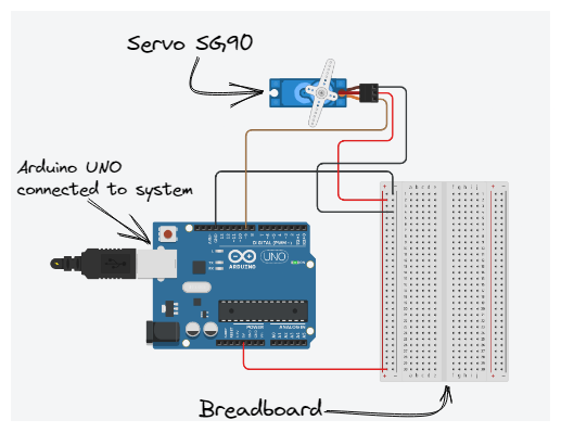
Note: Your connection of the Arduino board to the system will work as the power input to the present setup.
CODE LOGIC : We are using the “Servo.h” library that allows us to use functions that will help us to control the servo motor. This program aims to move the servo motor shaft from angle 0 to 180 and then return from angle 180 to turn 0 again. We are using two for loops, one for increasing the motor shaft angle position (from 0 to 180) and the second loop for returning the motor shaft to 0 (from 180 to 0). The servo's current angle will be continuously printed on the serial monitor.
Projects related to Servo Motors :
There are various projects which you can make by using servo motors from this link here, but I want to list some listed projects which you should try :
Stay in touch with us to expand your horizons to the world of robots!!
Follow MARS on GitHub, Hashnode, LinkedIn, and Instagram, Happy learning!! ✨


